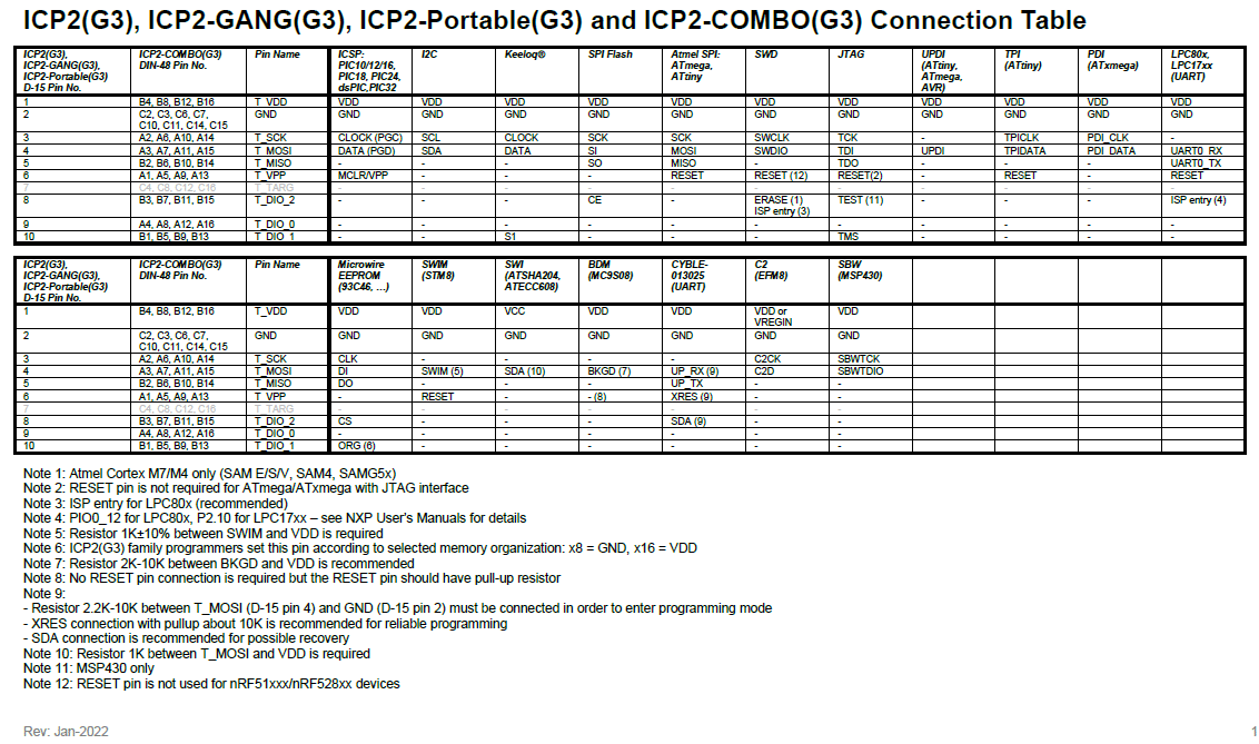
Yes, our ICP2 family programmers can operate in fully standalone mode. The programming environment (algorithm, hex file, settings, etc.) is transferred from PC to ICP non-volatile memory, then standalone programming is done using pins GO/PASS/FAIL. Additionally, ICP2-COMBO(G3) contains 3 hardware lines for environment selection
See connection table below:
Standard software allows to program up to 64 target devices simultaneously. Contact Softlog Systems at support@softlog.com if you need to program more than 64 devices at the same time
[A] Yes, ICP2(G3) and ICP2-Portable(G3) can be powered from USB line only. ICP2 family programmers automatically detect absence of 12V power supply and reduce Vdd maximum drive current
[B] ICP2-GANG(G3) and ICP2-COMBO(G3) should be always powered by their 12V power supplies
Most of target devices enter programming mode by applying Vdd voltage followed by Vpp one. Many target PCBs contain big capacitance (100-1000uF and more) on Vdd line which causes Vdd to rise slowly. Programmable Vdd-to-Vpp delay allows to keep correct sequence (Vdd, then Vpp)
– Validate that your brown-out reset IC can withstand 13V on its output
– Place resistor 1KΩ or more between output of the brown-out reset circuit IC and MCLR/RESET
– For complicated design contact us: support@softlog.com
Single channel mode allows to run separate channels in full PC-driven mode helping to debug your system
The security bit on SAMC/D/L/R devices can be programmed and then re-programmed (“erased”=chip erase) w/o limitations
Make the following sequence in ICP for Windows:
– ***Don’t*** use Wizards since they don’t contain operation with the Security Bit
– Make all settings (device, voltage, clock speed, etc.)
– Load HEX file. Note: in contrary to the most of other families the security bit is ***NOT*** a part of the HEX for SAMC/D/L/R devices
– On the Control Center set Security Bit = ON
– Now you can execute PC-driven programming or/and create PJ2 file (Environment-Save Environment As). The security bit will be saved as a part of the PJ2 file
ICP2 family programmers don’t require service since they don’t contain moving components
ICP2 programmers are designed for 24/7 operation. They are highly reliable due to the following hardware features:
[A] No electro-mechanical components with moving parts are used
[B] All target connector lines are protected in hardware as follows:
– VDD: hardware current limit, source current only, fast discharge circuit
– VPP: hardware current limit, PTC fuse with clamping diodes
– clock/data I/Os: high-power in-series resistors with clamping diodes
The Universal HEX file loader allows remapping of virtual addresses of the HEX file into physical or Softlog-format addresses – see examples below
Example for ATmega8, etc.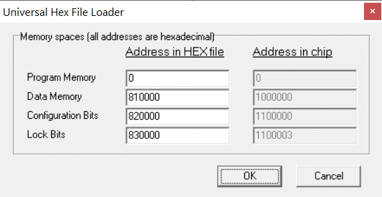
Example for ATtiny816, etc.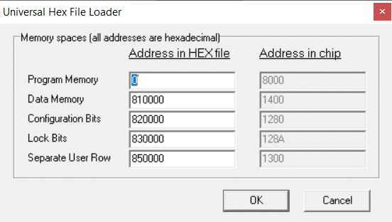
Make the following steps: 1. Generate ELF file containing all memories using Atmel Studio 2. Convert the ELF file into HEX using Atmel Utility “avr-objcopy.exe” or “objcopy.exe” which is located in “c:\Program Files (x86)\Atmel\Studio\7.0\toolchain\avr8\avr8-gnu-toolchain\avr\bin\”: objcopy -O ihex Input.elf Output.hex 3. Validate that the HEX contains records as shown below in red (all or partly) :1015B000BF93E0E0F0E1328131FDFDCFDC01A050CE :1015C000BC4E2C932DE924BF23E020830196BF91CC :0815D000AF910895F894FFCFDC :02000004008179 :1000000000000000000000000000000000000000F0 :1000100000000000000000000000000000000000E0 :02000004008278 :090000000905020000F6070000EA :02000004008377 :01000000C53A :00000001FF 4. Load Output.hex using File – Universal HEX Loader 5. Then you can save it by File – Save As (Export) and use later by File – Open (Import)
Battery life calculation is complicated since it depends on many conditions, but generally it should be enough for more than 1000 programming cycles.
The following number of programming cycles can be achieved using alkaline batteries (common condition: 30 seconds of idle time, battery capacity 2500mA*h):
– The best case for 5sec programming: no load, VDD=VPP=3.3V → ≈3000 cycles
– The worst case for 5sec programming: VDD=5V, VDD current = 40mA (load 120R); VPP=13V, VPP current = 13mA (load 1K) → ≈1600 cycles
– Big devices (256K and more, programming time 30 seconds) are powered from 3.3V therefore number of cycles in the worst case will be around 1000
[A] Maximum cable length depends on many parameters:
– Cable structure: unshielded separate wires are recommended to reduce crosstalk and capacitance
– Microcontroller type: there are microcontrollers which are sensitive to very small spikes on clock, data or/and reset/VPP line
– Target PCB: components around the target microcontroller and termination of clock/data lines affect communication between programmer unit and target
– Additional items may also affect entering programming mode
[B] We recommend “as short as possible” cables but we know that several customers use cables with more than 2 meters length
[C] You can add small capacitor about 33pF (22-47pF) between clock (pin 3) and GND (pin 2) on the ***target side*** of the cable
DLL Functions:
– IcpGangNumberBoxesSet
– IcpGangNumberBoxesGet
– IcpGangChannelSet
– IcpGangChannelGet
Advanced Command Line sections in INI file:
[Gang]
GangNumberBoxesSet
GangChannelsBox1
GangChannelsBox2
…
GangChannelsBox16
You can use DLL / Command Line software which contains new functions for box/channel manipulation
ADMIN and USER is exactly the same software (EXE) but the ADMIN setup contains small file “IcpSec.def” which causes slightly different behavior of the USER version:
– No ADMIN functions are shown
– “Select Product” and “Program” dialogs are automatically run
When ADMIN is installed on particular PC it’s nothing to do with the USER application, the USER application should be installed on the contract manufacturer (CM) side. Furthermore today you can avoid using USER application since all operations can be done with the Advanced Command Line which was developed for your needs.
The total process can be described as follows (R&D verification/validation steps are not shown):
– ADMIN: create SID file
– ADMIN: physically transfer SID to ICP2(G3)
– ADMIN: deliver ICP2(G3) to USER (CM)
– Advanced Command Line: generate SEN (secure environment) file based on your HEX and SID
– Send SEN to CM
CM transfers the SEN to ICP2(G3) by one of the following means:
– by Command Line or Advanced Command Line (switch /u)
– by ICP DLL function
– by Secure Programming Utility – as “Product”
– by Secure Programming Utility – direct transfer
At this point ICP2(G3) is ready for standalone programming (fully standalone or PC-controlled) by one of the following means:
– by Command Line or Advanced Command Line (switch /i)
– by ICP DLL function
– by Secure Programming Utility
– by ICP for Windows
– by GO button